Simulate Ned/Ned2 with Matlab
V.2.1

Difficulty: easy
Time: ~15 min
Note
- This tutorial is working from:
- The version v4.1.0 of the ned_ros_stack
Objectives
Being able to create content with Ned/Ned2 and Matlab
Visualize Ned/Ned2 model on Matlab and control it.
Requirements
Basic knowledge of Matlab
Basic knowledge in robotics and kinematics
Note
What you will need
Matlab
Robotics System Toolbox: https://fr.mathworks.com/products/robotics.html
3D model of Ned (URDF, STL, DAE)
Note
Although the robots are different, the 3D models are similar, so you can download the Ned model to simulate a Ned2.
Visualize Ned/Ned2 simulation
In this section you will be able to have a first application of Ned/Ned2 using Matlab. You will learn how to import the rigid body of Ned/Ned2 on Matlab.
It’s simple to import Ned/Ned2 on Matlab. For this, you just need to create a script, add the following lines to import the Ned’s URDF and put the STL/URDF/DAE files on the same folder as the script (as explained above).
clear All
clc

ned = importrobot("ned.urdf");
show(ned);
Result:
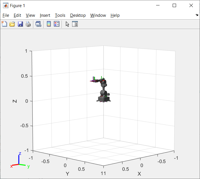
Ned/Ned2 Simulation first view
Then, you can change the view of the simulation by using some functions:
ned = importrobot("ned.urdf");
axes = show(ned);
axes.XLim=[-0.5,0.5];
axes.YLim=[-0.5,0.5];
axes.ZLim=[0,0.5];
campos([3,3,1]);
grid off;
Result:
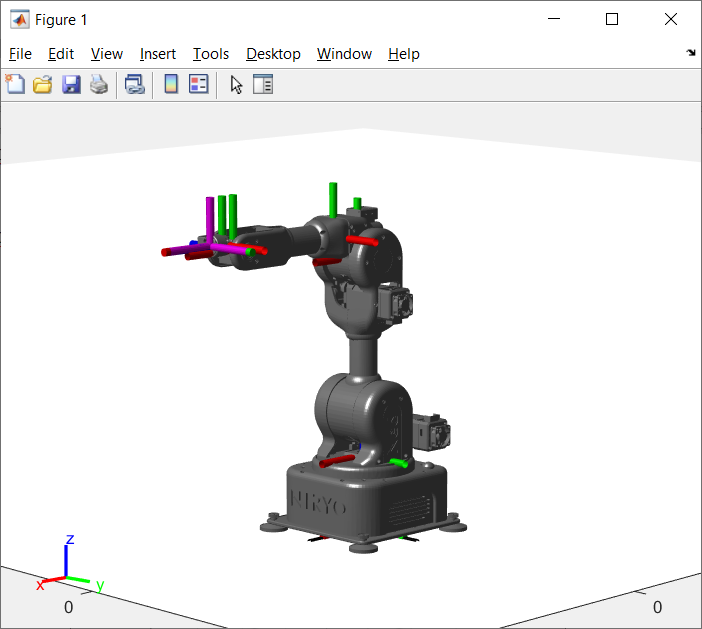
Ned/Ned2 Simulation improved view
Note
You can check the structure of Ned/Ned2 by using the following command:
showdetails(ned);

Details of Ned/Ned2 structure
Get the model of Ned/Ned2
Get the initial configuration of Ned/Ned2
Go back to the Matlab script you created and add the following line.
inititial_configuration = ned.homeConfiguration
Get the direct geometric model of Ned/Ned2
T1_2 = ned.Bodies{1,2}.Joint.JointToParentTransform;
T2_3 = ned.Bodies{1,3}.Joint.JointToParentTransform;
T3_4 = ned.Bodies{1,4}.Joint.JointToParentTransform;
T4_5 = ned.Bodies{1,5}.Joint.JointToParentTransform;
T5_6 = ned.Bodies{1,6}.Joint.JointToParentTransform;
T6_7 = ned.Bodies{1,7}.Joint.JointToParentTransform;
T7_8 = ned.Bodies{1,8}.Joint.JointToParentTransform;

T = T1_2*T2_3*T3_4*T4_5*T5_6*T6_7*T7_8;
You should have this matrix T:

Matrix T
Note
You can find more information about transformation matrices here.
eeoffset = 0
eeBody = robotics.RigidBody("end_effector")
setFixedTransform(eeBody.Joint, trvec2tform([eeoffset,0,0]))
addBody(niryo_one, eeBody, "tool_link");
T_M = getTransform(ned, ned.homeConfiguration,"end_effector","base_link")
You should have this matrix T_M:
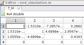
Matrix T_M
Note
The matrices T and T_M should be the same when comparing.
Get the inverse geometric model
Unlike the direct geometric model which purpose is to express the cartesian coordinates of the end effector considering the rotation angles of the joints, the inverse geometric model expresses the angular displace of the joints considering the cartesian coordinates of the end effector in a Galilean coordinate system.
ik = inverseKinematics("RigidBodyTree", ned);
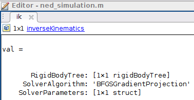
Inverse kinematics object
You can find more information about Matlab function above here: https://fr.mathworks.com/help/robotics/ref/inversekinematics-system-object.html
From a random position, find the required joint angles to reach the initial position
To do so, we will have to define:
Pose: the pose of the end effector, specified as an homogenous 4x4 transform matrix.
Weight: the weights on the error of the desired pose [r p y x y z].
InitialGuess: initial estimate of the robot configuration, specified as an array or a vector.
Add the following lines to your script:
weight = [0.1 0.1 0 1 1 1];
initialguess = ned.homeConfiguration
pose_M = [0.25 0 0.3];
tform = trvec2tform(pose_M);
configSoln = ik("end_effector", tform, weight,initialguess);
cell = struct2cell(configSoln);
Joint = cell(2,:,:);
matrixJoints = cell2mat(Joint);
With this code and because of the inverse geometric model of Ned/Ned2, you can see which movement it should do to reach the initial position [0.25,0,0.3].
Note
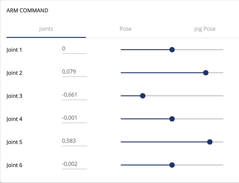
Joints values in Niryo Studio
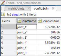
Joints values in Matlab
These short applications show you that you can use Ned/Ned2 with Matlab to learn robotics.
Make the simulation move
After compiling all the previous lines of code, type the following lines in order to see the new position of Ned/Ned2:
for i=1:6
   ned.Bodies{1,i+1}.Joint.HomePosition = Joint{1,1,i};
end
show(ned);
Now, you can make the simulation move by changing the coordinates of point M.
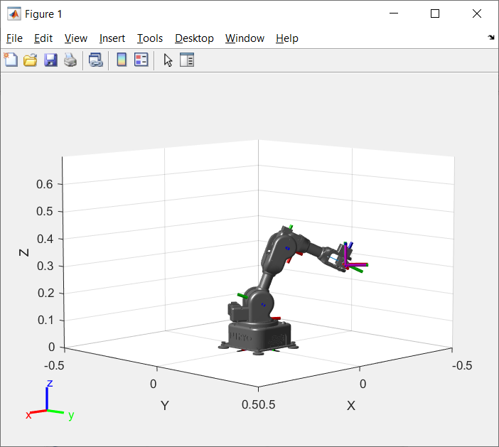
NED/Ned2 simulation in an other position
Now, if you want to see the simulation in motion, type the following code:
figure(1)
y=-0.10:0.02:0.10;
for j=1:length(y)
   pose_M=[0.25 y(j) 0.3];
   tform=trvec2tform(pose_M);
   configSoln=ik("end_effector",tform,weight,initialguess);
   cell=struct2cell(configSoln);
   Joint=cell(2,:,:);
   for i = 1:6
      ned.Bodies{1,i+1}.Joint.HomePosition = Joint{1,1,i};
   end
   axes=show(ned);
   axes.XLim=[-0.5,0.5];
   axes.YLim=[-0.5,0.5];
   axes.ZLim=[0,0.5];
   campos([4,0,0.5])
   grid off
   pause(0.01);
end
Result:
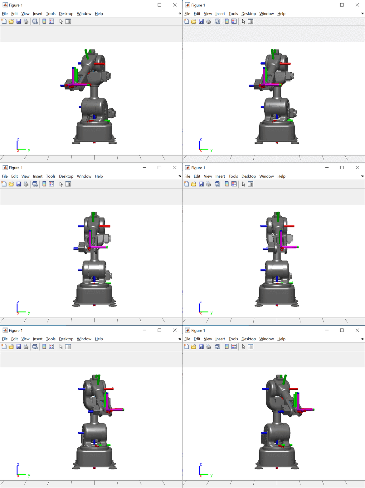
Simulation in motion
Note
Attention: the simulation does not work with all positions, especially those that are too close to the center (0,0,0).
Note
You can find all the information concerning the use of Ned/Ned2 with Matlab and the ROS Toolbox by following this tutorial below:
Or this one to control Ned/Ned2 with Matlab: