Direct control
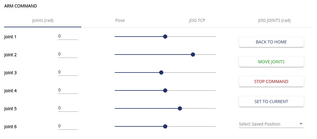
Arm command
On the ARM COMMAND section, you can move Ned’s arm directly either by moving the robot joint individually or by translating / rotating Ned pose.
You will find 4 main subsections that this documention will cover below, but we will start with the main buttons available.
Home Position
Click the “BACK TO HOME” button in order to move Ned to its home position.
Select Saved position
If you already saved a position, you can select it via the “Select Saved Position” scrolling menu. Once selected, it will upload joints value if your are in joints view, or pose if you are in pose view.
Then you can click on “MOVE JOINTS” or “MOVE POSE” to move the robot according to the selected joints/pose.
Stop command
The “STOP COMMAND” button stops Ned’s motion.
Joints
This method allows you to control each joint individually from its minimum to its maximum value (see the Robots specificities section).
If a joint reaches its joint limit, it can’t be driven any further.
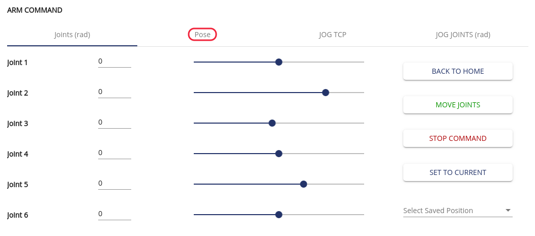
By clicking on the “SET TO CURRENT” button, you will refresh the interface to the actual joints values.
To perform a move joints, you need to:
Modify the values of the joints either by writing the desired joint value or by moving the cursor,
Click on the “MOVE JOINTS” button to execute the move command.
Once the command is done (success or not), you will get a notification at the bottom of the screen.
Important
At any time, you can cancel the current command execution by clicking on the “STOP COMMAND” button.
Pose
This panel gives you the possibility to move the pose of Ned’s TCP (Tool Center Point).
You can edit the values by clicking on them then use the “MOVE POSE” button.

JOG TCP
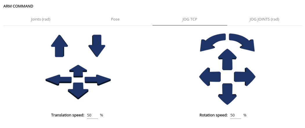
This panel will help you move Ned in a more visual way.
The TCP (Tool Center Point) of the robot is the center of the end effector.
Holding a translational arrow will make the robot follow its direction,
Holding a rotational arrow, will make the robot rotate around the TCP.
The robot will move until you release the button.
You can modify the speed of the jogs. A low value will give you more precision while a higher value will bring you faster to the position.
Hint
The performance of the jog TCP can be impacted by your network connection. We advise you to use an Ethernet connection to get the optimal communication and the best experience with the jog TCP feature.
JOG JOINTS
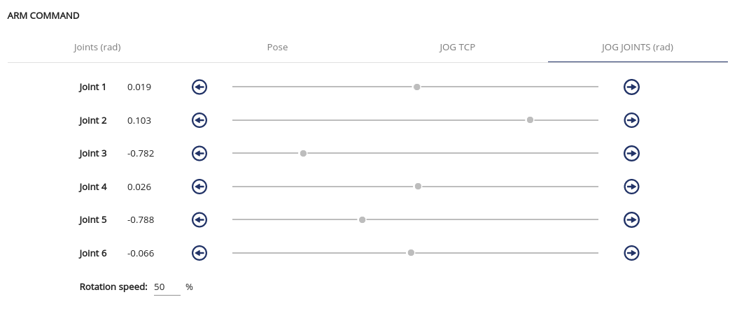
You can also switch to jog Joints on the ARM COMMAND panel.
The jog Joints allows you to control each joints of the robot by holding down one arrow.
The robot will move until you release the button.
You can also change the movement speed. A low value will give you more precision while a higher value will bring you faster to the position.
Hint
The performance of the jog joints can be impacted by your network connection. We advise you to use an Ethernet connection to get the optimal communication and the best experience with the jog Joints feature.
Tool command
The “SCAN” button will detect and add a tool if there is already a connected tool (with motor).
- If you have a gripper:
You can set the opening and closing speed by writing the value or by dragging the cursor (from 100 and 1000),
You can send open and close commands to the gripper by clicking “OPEN” and “CLOSE” buttons.
If you have a Vacuum Pump, the “ON” button will pull the air with the Vacuum Pump and the “OFF” button will pull the air out of the pump.

Digital I/O panel

You can monitor and set I/O signals from or to Ned. The “DIGITAL I/O PANEL” displays the current state of the I/O “SW1”, “SW2”, “GPIO1”, and “GPIO2” connectors on the back of Ned.

Note
Check the Electrical Interface for electrical and connection details.
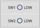
“SW1” and “SW2” connectors can be used to plug a fan, a motor, etc.
For “GPIO1” and “GPIO2”, you have, from left to right: GND, 5V, and 3 digital pins. The digital pins can be used to communicate with another device (ex: an Arduino board. Check out this tutorial to learn more about that).
Switches
The switches are already set as OUTPUT mode.
You can change the “SW1” and “SW2” states to “HIGH” or “LOW” by clicking the corresponding button.
GPIO
Warning
Make sure to read the Safety Precautions and the hardware manual before using the digital I/O of Ned.
A digital pin (GPIO) can be set as an INPUT or OUTPUT mode.
You can change the mode (INPUT or OUTPUT) and the state (LOW or HIGH) for each pin, by clicking on the corresponding mode and state on the “DIGITAL I/O PANEL”.
When the pin is set as an INPUT, you can read the state in this panel.
In OUTPUT mode, you can set the OUTPUT state of the pin (LOW or HIGH) by clicking on the corresponding button.
Note
By default, all the GPIO pins are in INPUT mode and HIGH state.
Electromagnet control
Make sure to read the Safety Precautions and the Hardware Manual before using the digital I/O of Ned.
The Electromagnet can be set up and controlled on the “DIGITAL I/O PANEL”.
You can connect the electromagnet on the GPIO1 or GPIO2 at the back of Ned (see Hardware Manual).
Then, you need to set up the digital I/O pin.
Select the pin where you connected your electromagnet cable.
Set this pin to OUTPUT.
Control your electromagnet by changing the state of the selected pin to LOW or HIGH.
Hint
If you are using the connector provided with the electromagnet, select 1A pin if you connect to the GPIO1 and 2A if you connect to the GPIO2.